Building Structures using the Model Wizard
Creating Load Combinations
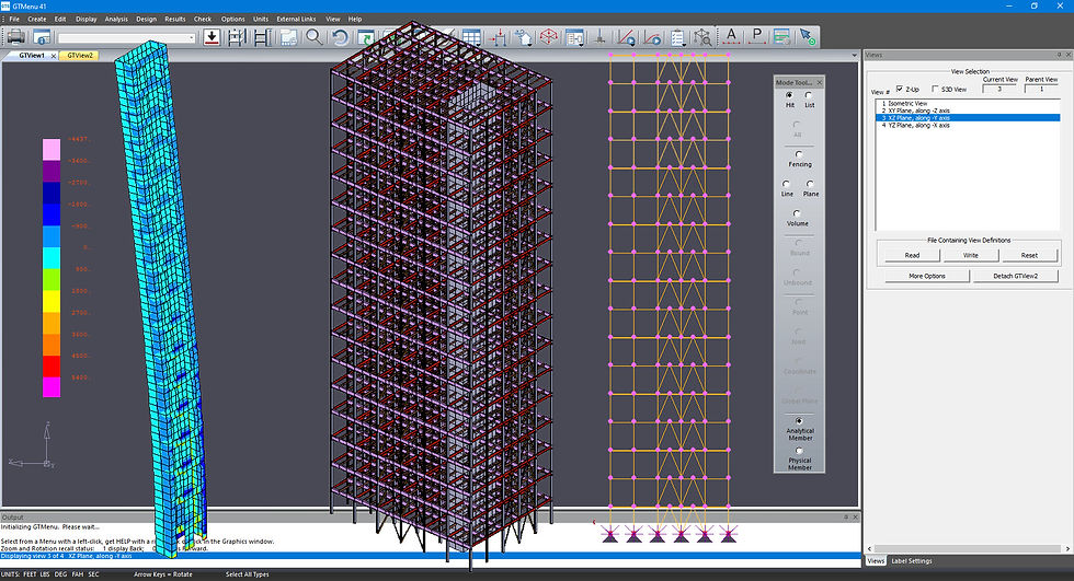
Modifying a Structural Model
Learn how to create a feasibility study, leveraging the model wizard tool to quickly create common structures using a parametric methodology. This results in the creation of a completely defined model ready for analysis and design.
It is essential that structural engineers check if structures can withstand the loads and forces, they will be subject to, in addition to regulatory codes and compliance. They must do this via multiple combinations, which can be a challenge to create and track. But leveraging the alphanumeric naming of loads and then designing and propagating basic load combinations can make this task quicker and easier.
Learn the possibilities for manipulation of a structural model in GT STRUDL. In addition to selecting members, know how to create a copy in the graphics and via the listing.
Report Builder
Integration between CADWorx, CAESAR II and
GT STRUDL
Using GT Menu for Finite Element Analysis
Engineers must create reports documenting their work for many reasons, such as peer review, client handover or project archiving. In the past, this involved exporting results to spreadsheets and word documents, then spending considerable time formatting this data into a readable format. GT STRUDL’s report builder enables engineers to quickly and easily create custom reports that are fully formatted and easy to read. Instead of a bulk dump of data, it is filtered down to the information the engineer would need to include in their report.
Even that information can be filtered only to include data on specific components or areas of a structure.
For structural engineers working on heavy industrial projects, piping loads are one of the most onerous loads to deal with. Historically, workflows have been for the pipe stress department to create load tables or print stress isometrics and manually notate loads, which are then passed to the structural department.
Learn how to create simple construction lines and points to create boundaries and mesh automatically to generate the finite element analysis model, including adding internal boundaries for holes.
Structural Model Modifications using Data Sheets
Combining Beam Analysis and Finite Element Analysis
Integration with CADWorx Structure Professional
Learn how a datasheet can be used to manipulate the structural model including live feedback in the graphical region.
Many engineers are required to perform finite element plate analysis along with traditional simple stick line beam analysis to model structures such as a concrete beam supporting a slab or stiffeners supporting a steel plate. In this video, you will learn how easy it is to model a finite element model based on an existing stick line model in GT STRUDL
Structural engineers should follow modern LEAN workflows that leverage interoperability. The most common reason for engineers not participating in these workflows is the quality of information transfer from the design department to engineering resulting in management hearing things like “it is faster for me to re-build the model myself than to clean up what comes from the CAD/design department.” Also, a challenge to LEAN workflows is how the structural engineering department passes information back to the designers. Design and engineering teams using GT STRUDL and CADWorx Structure can benefit from robust and well-thought-out interoperability, utilizing physical member definitions and both native input and industry-standard neutral files to not only have a usable analysis file from the design, but also allow the design department to review and approve or reject any suggested changes from the engineering department.